300ZX/Z31 front control arm conversion notes
1 post
• Page 1 of 1
300ZX/Z31 front control arm conversion notes
![]() by support » Tue Jul 15, 2014 10:24 am
by support » Tue Jul 15, 2014 10:24 am
This is a very simple modification, all you realistically need is a square, a sawzall, and if you don't have a welder, visit someone who can weld it for you...
The cutline should be between 95-100mm as measured from the inner end of the control arm; simply put, if the arm is placed on a table next to a wall, the cutline is measured horizontally from the wall at all points, with the control arm held flat to the table, and the inner end touching the wall.
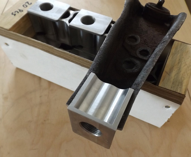
Once the cut is done, flip the arm on it's back, and test fit one of the weld blocks to see if the edges are all flush:
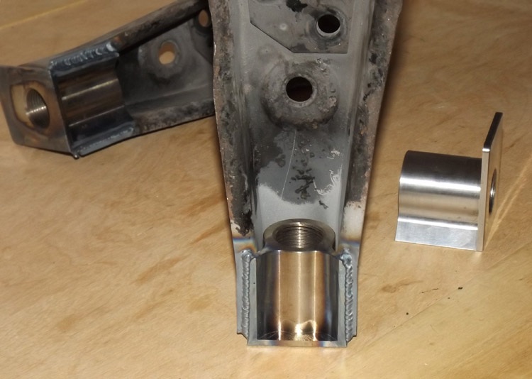
After verifying the cuts are good, checking both arms are close to equal, and you have removed all rust or grime from the arms, then have the corners edges tacked in place. Re-verify all the edges are still flush, then complete the welds. The design of the flange and "wings" keeps the heat well away from the threads as seen by the discoloration:
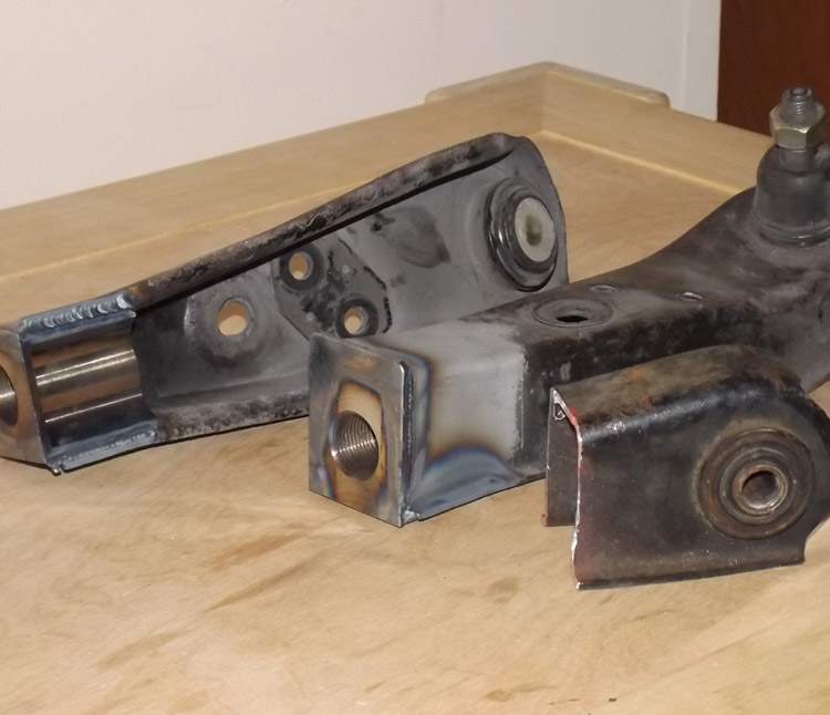
Once the welds are complete, it would be a great time to paint everything, a flux applicator brush works well for painting in behind the weld block. Two coats of a quality oil based rust paint is recommended, and using a heat lamp can help speed curing.
The next step is assembly, namely figuring out which bits go where, and how best to adjust it all. The logical starting point would be at the factory arm length, the leftover cut off sections can be used as a guide, but first the components go in...
There are 2 jam screws in the kit, these are like giant grub screws, with the 10mm hexagonal hole -- note that these are machined not broached, so the 10mm allen wrench (or allen socket adapter for a wrench) will be easiest to insert on the side with the drilled corners, it may be a tight fight and wiggling it will help. This jam screw gets threaded in from underneath the arm, from the side of the weld block closest to the balljoint, there will be plenty of room to use a 3/8" socket driver within the walls of the arm. Insert the screw until there is about 1 thread visible, it will be tightened later.
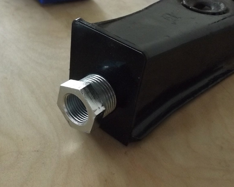
Next we install the double threaded adjuster from the outside of the arm, it gets inserted almost fully, with about 8-10mm of thread showing. Use the wall and a ruler to verify both double adjusters are equidistant from the balljoint, this isn't a high precision operation, the nearest 1-2mm should be adequate at this stage. The hex head of the double adjuster will take a 27mm wrench or socket.
Because of the zinc coating, the double adjuster will likely feel "too tight", spray some light oil like WD40 on the threads before inserting. Once you wind in and wind out the adjuster fully 2-3 times, it should feel noticeably smoother.
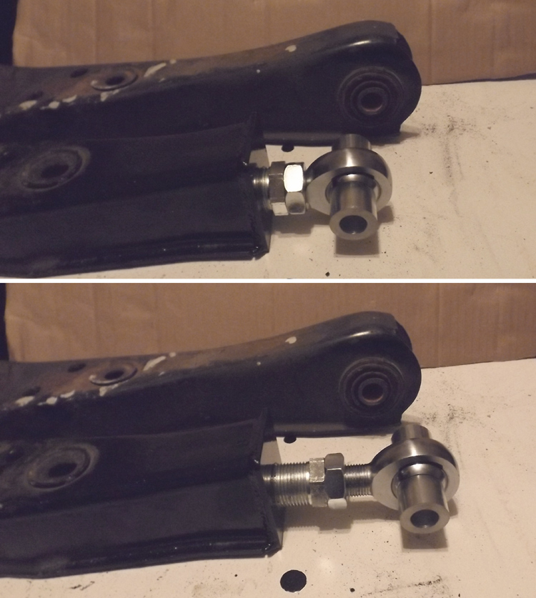
Then we install the rodend with the provided jam nut; the jam nut being spun all the way to the head of the rodend, until the last thread is just disappearing into the nut. With the jamnut near it's minimum length position, install the rodend into the double adjuster all the way, stop once the jam nut contacts with the adjuster.
Now using the off-cuts as a guide, hold the rodend and arm from turning, while unscrewing the double adjuster until desired length is achieved. Keep in mind that the default installation is to allow both shortening and lengthening the control arm, so the factory length will be towards the middle of adjustment range, but the total travel range is around 30mm from minimum to maximum safe extension. The double adjuster can be extended by more than 20mm, while the rodend can be extended more than 10mm.
Since there is more available thread on the adjuster, you may want to bias the length unscrewing the adjuster further than the rodend. At maximum extension on the rodend, there should be approximately the same mount of threads showing as the thickness of the nut. If at the desired position the rodend shows more thread than recommended, simply wind the rodend back into the adjuster about 5mm, and unscrew the double adjuster until the previous length is again achieved.
After everything is the correct length, tighten the jam screw underneath the arm with a 10mm allen socket, then tighten the jam nut on the rodend with a 29mm wrench. Torque both to between 35-45ft-lbs.
Finally, insert the rodend spacers, and mount the control arm as normal.
The cutline should be between 95-100mm as measured from the inner end of the control arm; simply put, if the arm is placed on a table next to a wall, the cutline is measured horizontally from the wall at all points, with the control arm held flat to the table, and the inner end touching the wall.
Once the cut is done, flip the arm on it's back, and test fit one of the weld blocks to see if the edges are all flush:
After verifying the cuts are good, checking both arms are close to equal, and you have removed all rust or grime from the arms, then have the corners edges tacked in place. Re-verify all the edges are still flush, then complete the welds. The design of the flange and "wings" keeps the heat well away from the threads as seen by the discoloration:
Once the welds are complete, it would be a great time to paint everything, a flux applicator brush works well for painting in behind the weld block. Two coats of a quality oil based rust paint is recommended, and using a heat lamp can help speed curing.
The next step is assembly, namely figuring out which bits go where, and how best to adjust it all. The logical starting point would be at the factory arm length, the leftover cut off sections can be used as a guide, but first the components go in...
There are 2 jam screws in the kit, these are like giant grub screws, with the 10mm hexagonal hole -- note that these are machined not broached, so the 10mm allen wrench (or allen socket adapter for a wrench) will be easiest to insert on the side with the drilled corners, it may be a tight fight and wiggling it will help. This jam screw gets threaded in from underneath the arm, from the side of the weld block closest to the balljoint, there will be plenty of room to use a 3/8" socket driver within the walls of the arm. Insert the screw until there is about 1 thread visible, it will be tightened later.
Next we install the double threaded adjuster from the outside of the arm, it gets inserted almost fully, with about 8-10mm of thread showing. Use the wall and a ruler to verify both double adjusters are equidistant from the balljoint, this isn't a high precision operation, the nearest 1-2mm should be adequate at this stage. The hex head of the double adjuster will take a 27mm wrench or socket.
Because of the zinc coating, the double adjuster will likely feel "too tight", spray some light oil like WD40 on the threads before inserting. Once you wind in and wind out the adjuster fully 2-3 times, it should feel noticeably smoother.
Then we install the rodend with the provided jam nut; the jam nut being spun all the way to the head of the rodend, until the last thread is just disappearing into the nut. With the jamnut near it's minimum length position, install the rodend into the double adjuster all the way, stop once the jam nut contacts with the adjuster.
Now using the off-cuts as a guide, hold the rodend and arm from turning, while unscrewing the double adjuster until desired length is achieved. Keep in mind that the default installation is to allow both shortening and lengthening the control arm, so the factory length will be towards the middle of adjustment range, but the total travel range is around 30mm from minimum to maximum safe extension. The double adjuster can be extended by more than 20mm, while the rodend can be extended more than 10mm.
Since there is more available thread on the adjuster, you may want to bias the length unscrewing the adjuster further than the rodend. At maximum extension on the rodend, there should be approximately the same mount of threads showing as the thickness of the nut. If at the desired position the rodend shows more thread than recommended, simply wind the rodend back into the adjuster about 5mm, and unscrew the double adjuster until the previous length is again achieved.
After everything is the correct length, tighten the jam screw underneath the arm with a 10mm allen socket, then tighten the jam nut on the rodend with a 29mm wrench. Torque both to between 35-45ft-lbs.
Finally, insert the rodend spacers, and mount the control arm as normal.
1 post
• Page 1 of 1
Return to Product Support/Feedback
Who is online
Users browsing this forum: No registered users and 1 guest