Z31-to-S13 front coilover adapter fitment when trimmed
2 posts
• Page 1 of 1
Z31-to-S13 front coilover adapter fitment when trimmed
![]() by support » Wed Jul 09, 2014 4:17 pm
by support » Wed Jul 09, 2014 4:17 pm
Trimming the blade or reinforcement buttress can help improve coilover compatibility, as some coilovers come with diminutive brackets that try to keep the strut body very close to the mount, but most drifting oriented coilovers will not have this problem.
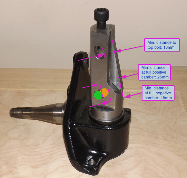
Once trimmed the adapter's minimum strut to bolt clearance changes, the clearance gain is proportionally greater as camber adjustment moves negative, which means maximum negative position yields the easiest fitment.
Here's a diagram for fitment, measure the intended coilover body with a bolt in each hole, the measurement should be taken at the center where the body is most crowned inside the bracket... the distance between the body and the inner edge of the bolt equals the clearance to compare:
Re: S13 coilover adapter fitment and compatibility
![]() by support » Wed Jul 09, 2014 4:30 pm
by support » Wed Jul 09, 2014 4:30 pm
The bolt installed in the top of the adapter is for marking camber for disassembly, and subsequent re-assembly.
A good tip would be to have everything aligned, then tighten a screw (M12x1.25) as far as it goes until hitting the through-bolt, note the number of exposed threads, then with the screw removed, trim the same number of threads from the end... install to test if the cut was correct, trim additional material if not, repeat as required.
Essentially, the installer can make various set screws for specific camber settings, such as a street oriented 1-1.5 degree negative set screw, and a more track oriented 2.5-3.5 degree screw, or perhaps a more extreme setting for drifting.
The possibility exists that the left and right coilover adapters don't have the exact same height above the slots, so it would be wise to check any set screw on both sides. If any variation is found, simply create an alternate set of screws for the other side.
A quick method to marking the set screws might be to spray paint the tops, the camber settings could correspond to various shades of colour to denote depth/degree at a glance, with perhaps a uniquely painted shank or coloured dot to denote LEFT, if the a second set for the RIGHT side is necessary.
2 posts
• Page 1 of 1
Return to Product Support/Feedback
Who is online
Users browsing this forum: No registered users and 1 guest